res·o·nance: entry #3
- Sophia Schulz
- May 21, 2025
- 7 min read

Updated: Nov 20, 2025
small-scale installation prototype complete! + other updates
A quick recap of where I left off with my last entry...
I shared my acceptance into the Blackbird Protostars Season 9 Cohort (which has just wrapped up with our final showcase on May 15th!),
I shared some ideas I had for installations in the exhibit,
I summarised my research into self and mutual capacitance touch sensors, and
I started creating CAD files for lasercut stencils that I could use to make my own versions of these sensors.
TL;DR for this entry:
I created an Instagram account for the project: @resonance.nz
I got a friend involved in the project — he'll be working on the soundscape installation mentioned in the last blog entry!
I tested the mutual and self-capacitance sensors I made using the stencils: self-capacitance worked, mutual... not so much
I switched gears and developed a small-scale prototype of an installation, just in time for the Protostars showcase — it's a proximity-controlled interactive LED display, featuring vintage slide films!
I've opened up applications for Participating Artists — apply here
Read through the entire blog entry below for more details on how I've executed the above things, and what my next steps are for the project!
so... where's res·o·nance at right now?
Thanks to Protostars, I've been focused on Building in Public and getting some community engagement — this means I've created an Instagram account for the project (shameless plug @resonance.nz) and have started publicly sharing about my progress prototyping some of the installations! I've made one short video so far (with more in the works) specifically showing the development of the self-capacitance touch slider and using it to control a string of LEDs (so yes, the self-capacitance slider explained in the previous blog does work!).
Thanks to Building in Public, a friend of mine became interested in the project and will be joining as a Participating Artist! He's interested in sound and music especially, so will be developing a soundscape installation similar to the idea described in the previous blog. After some insightful discussions together, I decided to open up the project to the public... more on this at the end of the blog!
what happened with those sensors you explained so heavily last time?
As previously touched on, the self-capacitance sensor I made did end up working! Considering no filtering was involved, the results were fairly smooth (partially thanks to ESP32's built-in capacitive touch sensing pins, which from my understanding handle all the grounding for self-capacitance, as I didn't need to add my own external ground). I created a slider with 4 electrodes (4 different touch surfaces) in an interleaved pattern to form a slider as explained in the previous blog, and using this to control 4 LEDs in a row which worked nicely. What I found interesting though, is that I was able to employ multi-touch with this slider — I wouldn't expect it to work too nicely in a grid, but in the linear slider shape it seems to be pretty reliable!
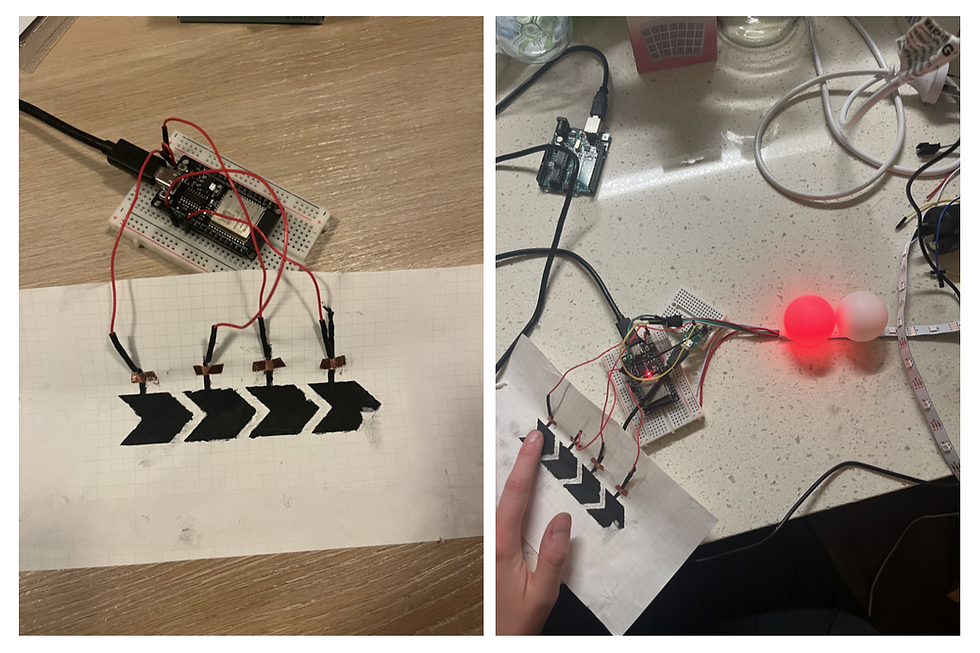
As for the mutual capacitance sensor, I created a 2x2 grid of electrodes using methods explained in the previous blog. However, the resulting data from testing the sensor was extremely noisy and likely requires some additional filtering and refinement of the prototype itself. I've decided that such a sensor, especially one made from scratch, would likely be too unreliable for a full-scale light installation as the user experience would be very frustrating (a lot of factors affect finger capacitance, likely resulting in some variability which isn't too fun from a user's point of view).

In the end, I felt that controlling lights from a single sensor forces a degree of separation between the user and the exhibit, introducing a barrier to interactivity that I didn't enjoy — you're forced to stay in one place, resulting in a much more passive interaction than I wanted. I figured the installation would be a lot more engaging if the user could explore the exhibit through greater movement, so I decided to pivot to a different kind of sensor: proximity sensors! I plan to use the self-capacitance (and maybe even the mutual capacitance) sensors for the smaller, education-focused adjoining installation alongside other sensors, also explained in the previous blog entry.
so what's this small-scale prototype you speak of?
In short, it's a proximity-controlled interactive LED display featuring vintage slide films!

Before reading on, if you want to see a process video of me making the prototype, you can check it out on our Instagram here: https://www.instagram.com/p/DNfXydgxBCT/
As mentioned above, I decided to pivot to using proximity sensors for this installation to promote a greater sense of interactivity. To start simple when it came to prototyping, I focused on developing an LED matrix that would be controlled by these proximity sensors. However, I felt that LED matrix-based displays have been done quite often before, so I tried to find a way to make it more artistic and interesting. This is where the diffusing medium came in: I first experimented with using ping pong balls, but didn't like how ornamental and plain they looked. I then recalled seeing some old vintage slide films in an antique store, which can be viewed using a light projecting device — or by taping parchment behind them and putting a light source behind the parchment paper, as I discovered!
I especially loved adding the slide films as it incorporating my love of photography as a storytelling element into the exhibition. Additionally, it gave the interactivity of the proximity control an added purpose: revealing each individual film and the picture it depicted through waving your hand close to it, thus adding a sense of discovery to the installation.
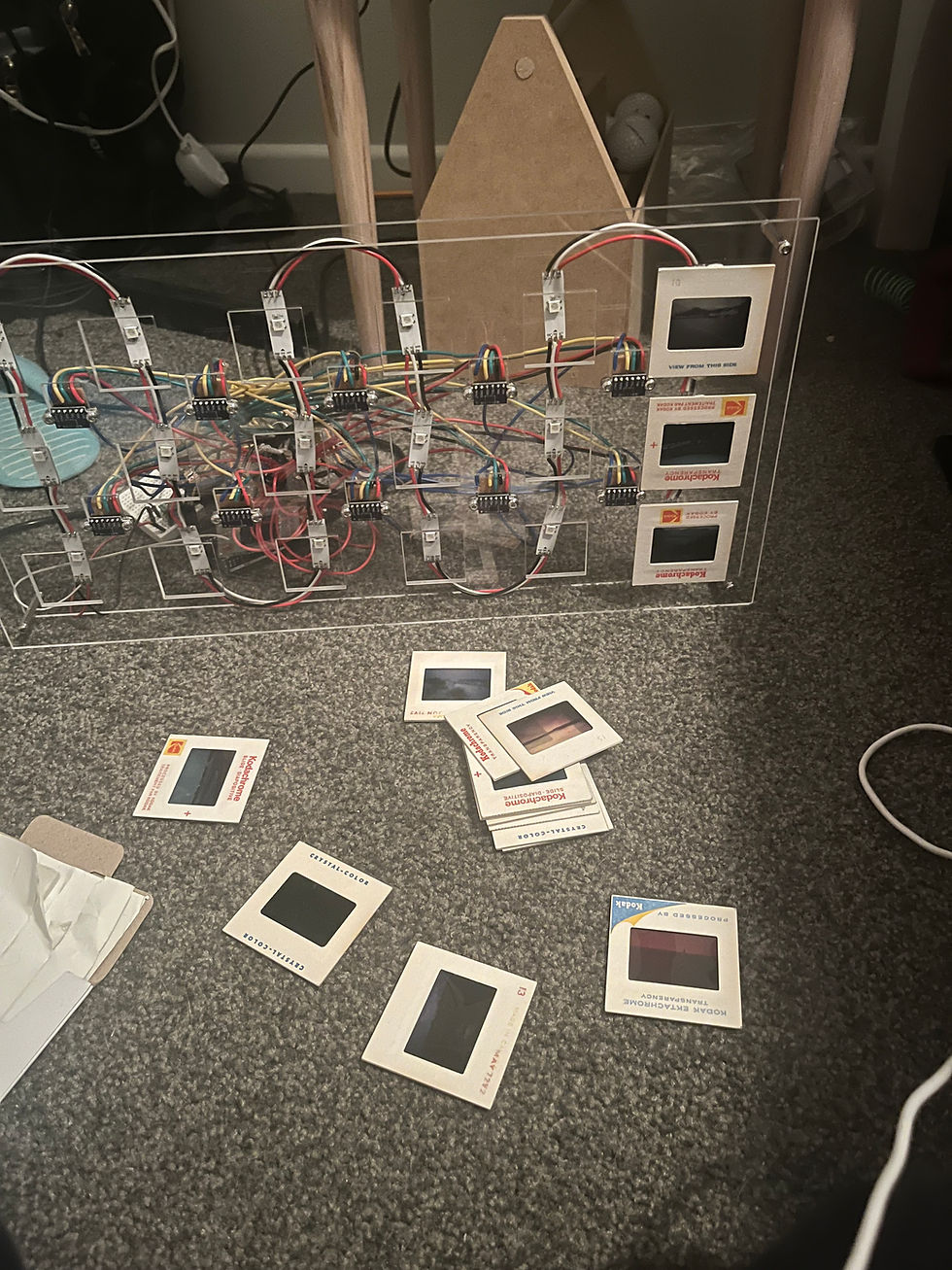
To make a small-scale prototype in time for the Protostars showcase (once I had settled on the idea, I had about 4 weeks to make it), I chose to create a matrix with 18 LEDs and 10 sensors — this would allow me to use one microcontroller for the entire panel, given the number of separate pins required to control that many sensors.
For the proximity sensor specifically, I chose Time of Flight (ToF) sensors as I found them to be much more accurate and reliable than IR or ultrasonic sensors, while having quite a small footprint, better range, and little to no interference with adjacent sensors' readings. This made them ideal for use in a large matrix display! I also preferred these over other sensing methods such as LiDAR or camera-based detection, as the sensors are more tangible and easier to see up close. This offers a stripped-down exhibit that aids in educating visitors on how sensors work, which offers the learning component of this installation!
All the materials used are as follows:
18x WS2812B individually addressable LEDs
10x VL53L0X ToF sensors
Arduino Uno as the microcontroller
18 vintage slide films (eg. Kodak)
Parchment paper behind each slide film to diffuse light
Lasercut acrylic for the frame
Many many (too many) wires and perfboard and solder...
5V, 3A power supply (a bit overkill for the current draw but doesn't hurt)
I'll save the detailed explanation of how the whole setup works for another post, but in short:
Each LED's brightness and colour can be individually controlled, even as all of them are wired together, thus only requiring one data pin for the microcontroller.
Each sensor is placed between the LEDs, so each sensor controls 4 adjacent LEDs.
This results in some overlap, where some LEDs are controlled by multiple sensors; the microcontroller handles any conflicts by taking the smallest distance reading from the conflicting sensors and assigning the respective brightness to that LED.
The brightness of the LED is proportional to the distance reading of its associated sensor — the closer, the brighter.
...with some added code to fade the brightness nicely for a more aesthetic appearance!
All of the sensors run on the same I2C communication bus which makes wiring fairly simple: essentially, all the sensors share the same SCL and SDA lines to the microcontroller.
In order to receive data from each sensor individually, the ToF sensors have an XSHUT line — all of these lines must be pulled LOW initially, then each one pulled HIGH one by one to set a unique address for each device. This allows them to be differentiated on the I2C bus.
Thus, the upper limit for the number of sensors communicating with one microcontroller was the number of pins available on that board.
And that's the shorthand explanation of how the installation works! See the video demonstration of the display below:
what's next for res·o·nance?
An obvious next step is building up the LED display further, as I imagine it to be quite a large installation, but I first need to figure out how to create one more efficiently (both in terms of time and costs). In the meantime, my main goal is to reach more people regarding the project and to get some involvement besides myself ;)
What this means is... I'm looking for Participating Artists to join the project and contribute some of the installations to be shown in the exhibition! I have an application (linked here) that is available for anyone to apply to — no prior experience or qualifications required, just an interest in STEM and Art and creating public-facing interactive works! If that sounds like you or someone you know, please apply — I'd love to hear from those who are interested in contributing to the project :)

Aside from that, I will also be promoting applications for a graphic designer soon as well, which will help build up the branding of the project as well as the typography to be used in the exhibition itself.
To gain more community engagement, I've been sharing my work with the University of Auckland's Makerclub, and have received interest in running a workshop to create a large community-contributed art tech installation. Stay tuned for more on that in the future!
Till next time,
~ Sophia


Comments